Lab Noise Floor
With the doors closed, and “pass-through” tubes stuffed with foam, we measured around 6.3dBA – or once again at the published noise floor of the microphone.
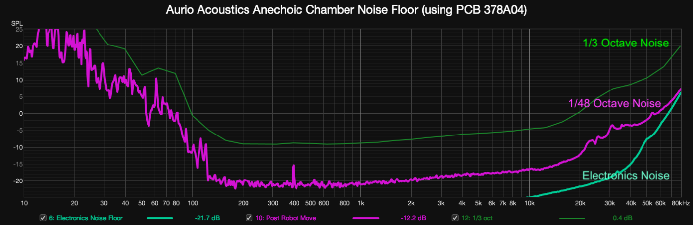
Until recently our quietest microphone had a 23dBA self noise – when attempting to measure lab background noise we’d get around 23dBA. In order to better assess our noise floor we rented a PCB 378A04 Low Noise 1/2″ Microphone from The Modal Shop (the process was easy and quick).
With the doors closed, and “pass-through” tubes stuffed with foam, we measured around 6.3dBA – or once again at the published noise floor of the microphone. A few statistics for those interested:
- A-weighted noise level (mid-day, on a weekday): 6.1-6.4dBA
- C-weighted noise level (mid-day, weekday): <33dBC
- Below 0dB (1/3 octave RTA): 100Hz – 19.4kHz
- Electronics noise floor (this calibration): -3.2dBA, -3.8dBC
- 8 to 15dB below measured/mic noise level
Several things contribute to our low noise floor:
- Site: We’re in building where the only “mechanicals” (motors, pumps, etc.) sharing a foundation with our lab are our own HVAC (and refrigerator and espresso machine). We can “go quiet” with the press of a button. We’re in Hollister, MO (small town) in the Ozarks, about a mile from the highway, in a small valley.
- Construction: We worked with Ted at Soundproofing Company Inc and Woodstone Builders to design and build a room-within-a-room (air gapped) enclosure for the chamber. We have a 6″ air-gap, and “floating” walls and a suspended or floating ceiling. All inner & outer walls, ceiling, and HVAC chases are double-drywall with Green Glue (80 gallons!). Outlets are sealed with putty pads Insulated HVAC ducts are treated with Noico run within previously mentioned double-wall chases.
Stay tuned for updated c-weighted noise levels made in the evening or weekend (with less traffic, and less noise in the industrial park).
Loudspeaker Anechoic Evaluations
Aurio Acoustics Loudspeaker Anechoic Evaluations focus on measurements outlined in CTA-2034.
| Loudspeaker Evaluation | Detail | Price* |
|---|---|---|
| System On-Axis SPL Response & Impedance | System 2.83Vrms, 1m Response, & Impedance (CTA-2034) | $1000 |
| System Directivity Responses | On-axis, Listening Window, Early Reflections & Total Power from horizontal & vertical radiation measurement (CTA-2034) | $1500 |
| System Max SPL & Max Input Voltage | Evaluate Maximum Usable Continuous Output SPL, Max Input Voltage and Recommended Amplifier Power (CTA-2034) | $1500 |
| 2-Way Speaker Driver On-Axis Responses & Impedance | Woofer & Tweeter SPL and Impedance (in enclosure, for crossover design) | $1200 |
| 3-way Speaker Driver On-Axis Response & Impedance | Woofer, Mid & Tweeter SPL and Impedance (in enclosure, for crossover design) | $1500 |
| Speaker or System ½ Space Response & Impedance | On-axis, 30-degree off-axis, 60-degree off-axis response (IEC Baffle) | $1000 |
System On-Axis SPL Response & Impedance
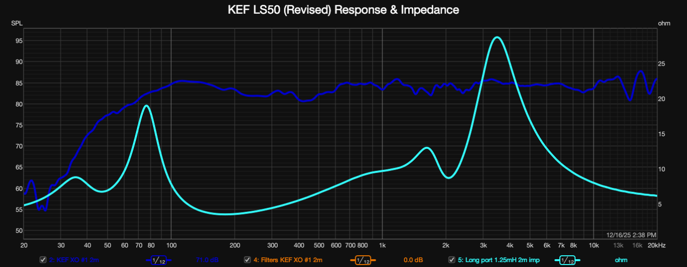
System Frequency Response (or SPL Response Magnitude) is typically specified with 2.83Vrms Input (per CTA-2034). Unless otherwise specified, Aurio Acoustics:
- Microphone positioned at 2.0m distance – response is corrected to 1.0m equivalent (+6.02dB)
- Microphone is aligned with tweeter axis
System Directivity Responses
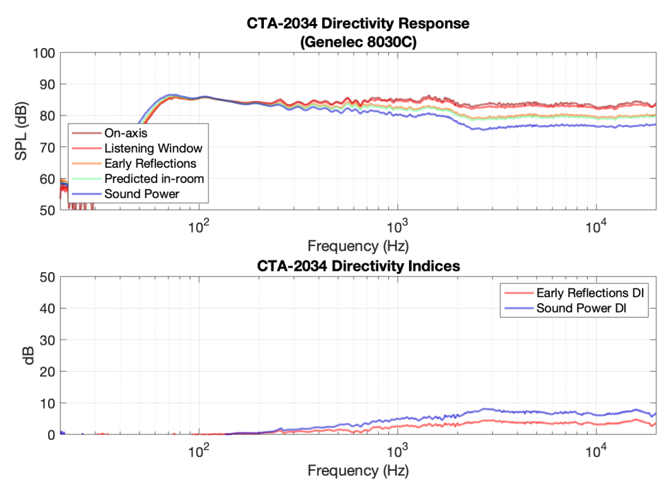
System Directivity Responses consists of 2 plots summarizing 70 measurements made of the horizontal and vertical radiation pattern of the speaker. Directivity Response and Directivity Index allow evaluation of both source quality (directivity) and source tuning (spectral balance), as well as prediction of typical in-room response.
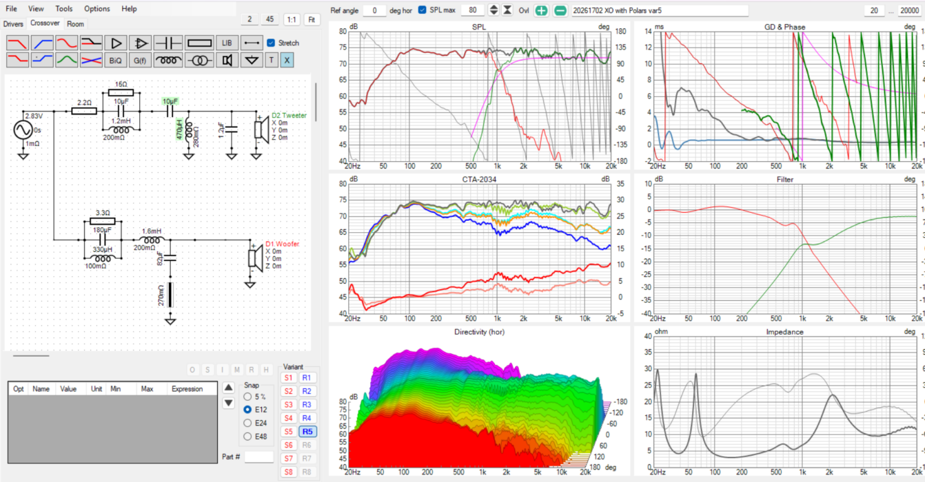
Two-Way Speaker Driver On-Axis & Impedance
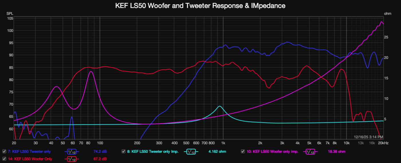
Developing a passive crossover for a loudspeaker requires characterization of Frequency Response (SPL complex magnitude vs Frequency) and complex Impedance (vs Frequency) at a nominal input voltage. Unless otherwise specified, Aurio Acoustics:
- Drivers are measured in enclosure*
- Microphone positioned at 2.0m distance – response is corrected to 1.0m equivalent (+6.02dB)
- Microphone is aligned with tweeter axis
- Input Voltage is 1.0Vrms (corrected to 2.83Vrms +9.04dB)
*Contact us if your enclosure is in development, or if your speaker is only a concept. We can help design and fabricate enclosures, and test.
Advanced
For those who prefer to work with horizontal and vertical radiation pattern data to develop crossovers, this is available. Contact us to discuss preferred measurement resolution, data format, etc.